Butt welding
Introduction
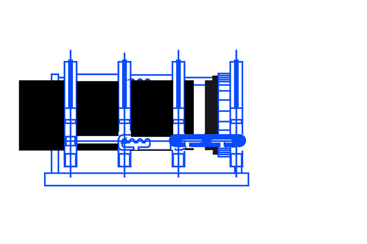
The PT series machines are able to weld all types of pipes, fittings and stub ends existing on the market today, the various possible types of welding are listed below:
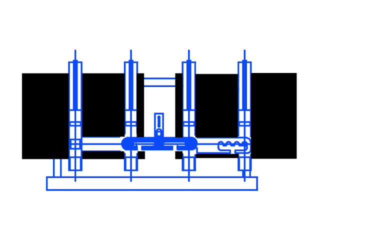
1) Welding pipe to pipe with the original configuration.
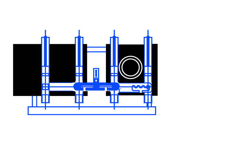
2) Welding long spigot fitting with pipe with the original configuration.
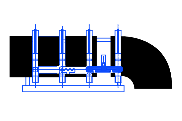
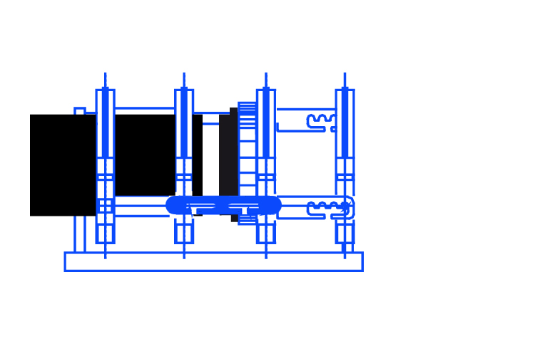
3) Welding of pipe with fitting or with short spigot bend. To carry out these weldings it is necessary to remove the spacer and use them to fix the mobile clamp to the mobile carriage. To facilitate the fixing of the short spigot bends, the use of a narrow upper clamp is recommended.
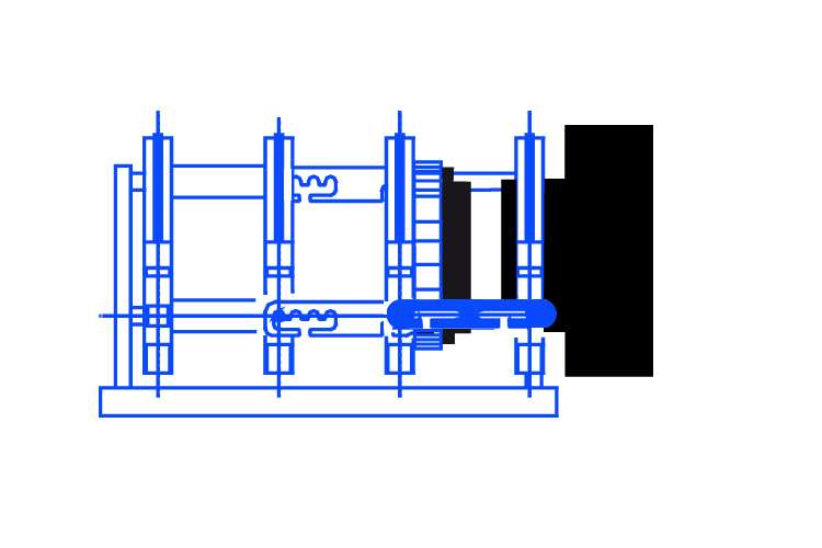
4) Fittings with stub end welding; the configuration of the basic machine is the same as the previous one, for welding the short spigot stub end the stub end device is required, consisting of an aluminum disc on the surface of which the external diameters of the stub end are punched and four clamps that slide into the appropriate housings. The clamps are locked to the mark corresponding to the diameter using bolts. The folder is fixed to the accessory by tightening the four screws so that they press on its external surface, guaranteeing its locking. The stub end device is provided with a ring which allows it to be mounted in any of the vices
5) Welding of pipe with stub end, in this case welds can be carried out with two configurations.
6) Welding of pipe with stub end, in this case welds can be carried out with two configurations.
Positioning and preparation of the welding machine
During use on construction sites, the use of special roller conveyors is recommended to facilitate the sliding of the pipes to be welded and to avoid the machine excessive efforts.
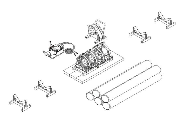
Place the machine components on a flat and regular surface, if necessary use wooden panels. The recommended arrangement of the components is shown in the figure.
Connect the hydraulic unit to the basic machine with the appropriate quick couplers.
Connect the hydraulic unit, milling device and heating mirror plate to the power point having ensured that the supply voltage matches their voltage of the machine within a 10%.
Attention, the heating mirror is starting to heat up!
Adjust the temperature of the heating mirror according to the thickness of the diameter and the material of the pipe to be welded (check your reference welding norm).
Select the reductions corresponding to the diameter of the pipe to be welded (the diameter value is punched on the reductions themselves),
assemble the eight half-rings by inserting them in the housing slots of the clanps and fixing them with the appropriate fixing system.
Some set of reducers includes two “narrow” half rings to facilitate gripping of short spigot fittings.
Alignment and milling
Prepare the mobile trolley in the fully open position.
Remove the upper clamps by loosening the tie rod nuts.
Position the two pipes/fittings to be welded being careful to leave sufficient space for the introduction of the milling device, reassemble the upper clamps and tighten the nuts.
Check the alignment of the pipes/fittings by bringing the surfaces to be welded together, any misalignments can be corrected by acting on the central clamps tie rod nuts or by rotating the pipes. Maximum offset cannot exceed 10% of pipe/fitting thickness up to a maximum of 2mm.
Clean the ends of the pipes/fittings by completely removing all traces of dust and dirt, if necessary clean with a suitable detergent.
Insert the milling device between the surfaces to be welded by inserting it into the appropriate slots in the basis machine, insert the safety pin and start the engine.
Slowly bring the ends of the pipes/fittings to be welded to the cutter blades which will begin to remove material, if this does not happen increase slightly the pressure (excessive pressure can burn the motor). Milling can be considered finished when the chips come out continuously and homogeneously on both sides and the chip width is equal to the thickness of the pipe/fitting. Turn off the milling device and put it back in its support.
Bring the surfaces to be welded into contact and check that any detachment is less than the limits shown in the table below.
| Outer diameter (mm)400 | Maximum gap (mm)0.51.0 |
Detection of the drag pressure
Before starting the welding cycle it is necessary to measure the drag pressure value, this value must be added to the welding pressures values contained in your reference welding norm. The value of the drag pressure depends on the welding operating conditions (e.g. length and weight of the pipe to be dragged, general conditions of the machine, ambient working temperature, etc.).
How to detect drag pressure?
- Fully open the trolleys of the machine by acting on the lever as indicated in the manual.
- Turn the pressure regulator knob anti-clockwise as far as it will go.
- Turn the pressure by-pass lever clockwise as far as it will go.
- Move the lever to the trolley closing position (the trolleys do not close as there is zero pressure).
- Slowly turn the pressure regulator knob clockwise until the trolleys slowly begin to move.
- During the movement of the trolleys, read the relative pressure on the pressure gauge (=drag pressure).
The welding cycle
FOR THE SUCCESS OF WELDING, THE MACHINE MUST BE USED ONLY BY SKILLED PERSONNEL.
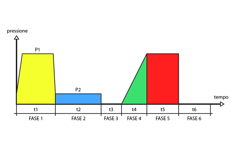
The welding cycle is divided into 6 distinct PHASES:
PHASE 1 Approach and equalizing (under pressure)
Insert the heating mirror between the pipes to be welded, rotate the heating mirror detachment towards the inside of the machine, fitting the support fork into it. increase the pressure by acting on the lever and with the distributor lever in the hooked position. The pressure value can be read on the pressure gauge.
This phase ends after a time t 1 as soon as a ring of molten material (bead) appears on the ends to be welded, the height of which is indicated in the welding tables.
PHASE 2 Heat up
When the bead with a proper height appears, the pressure is reduced by turning the lever anticlockwise and kept constant for a time t 2
PHASE 3 Heating mirror removal
Once the time t 2 has elapsed, the pressure must be brought to zero (by turning lever E anticlockwise) and the two sides of the pipes to be welded must be quickly moved away (by bringing the distributor lever to the open position) to allow removal of the hating mirror. It is important to check that the heating mirror detachment is positioned towards the outside of the machine after having removed the heating mirror.
Bring the two surfaces to be welded together by closing the trolleys and acting on the by-pass lever to obtain a pressure slightly higher than the drive pressure (so as not to have a sudden outflow of material at the moment of contact between the two surfaces).
PHASE 4 Reaching the welding pressure
Once the contact between the two surfaces to be welded has taken place, the pressure must be brought to gradual and continuous to the P5 pressure value of PHASE 5 in one time t 4 turning the by-pass lever clockwise and with the distributor lever in the carriage closing position
PHASE 5 Pressure welding
The pressure value reached in the previous phase must be maintained for a time equal to t 5. During this phase, the distributor lever must be brought to the neutral position as the pressure value is maintained even with the engine off.
Once the welding has been completed, before loosening the upper clamps, the pressure must be brought to zero.
PHASE 6 Rest or cool down time (outside the machine)
Once the pressure welding phase has been completed and the product has been removed from the machine, it is good practice to wait a further period of time t 6 (minutes) before stressing the welding (putting under pressure, heavy transport or other).